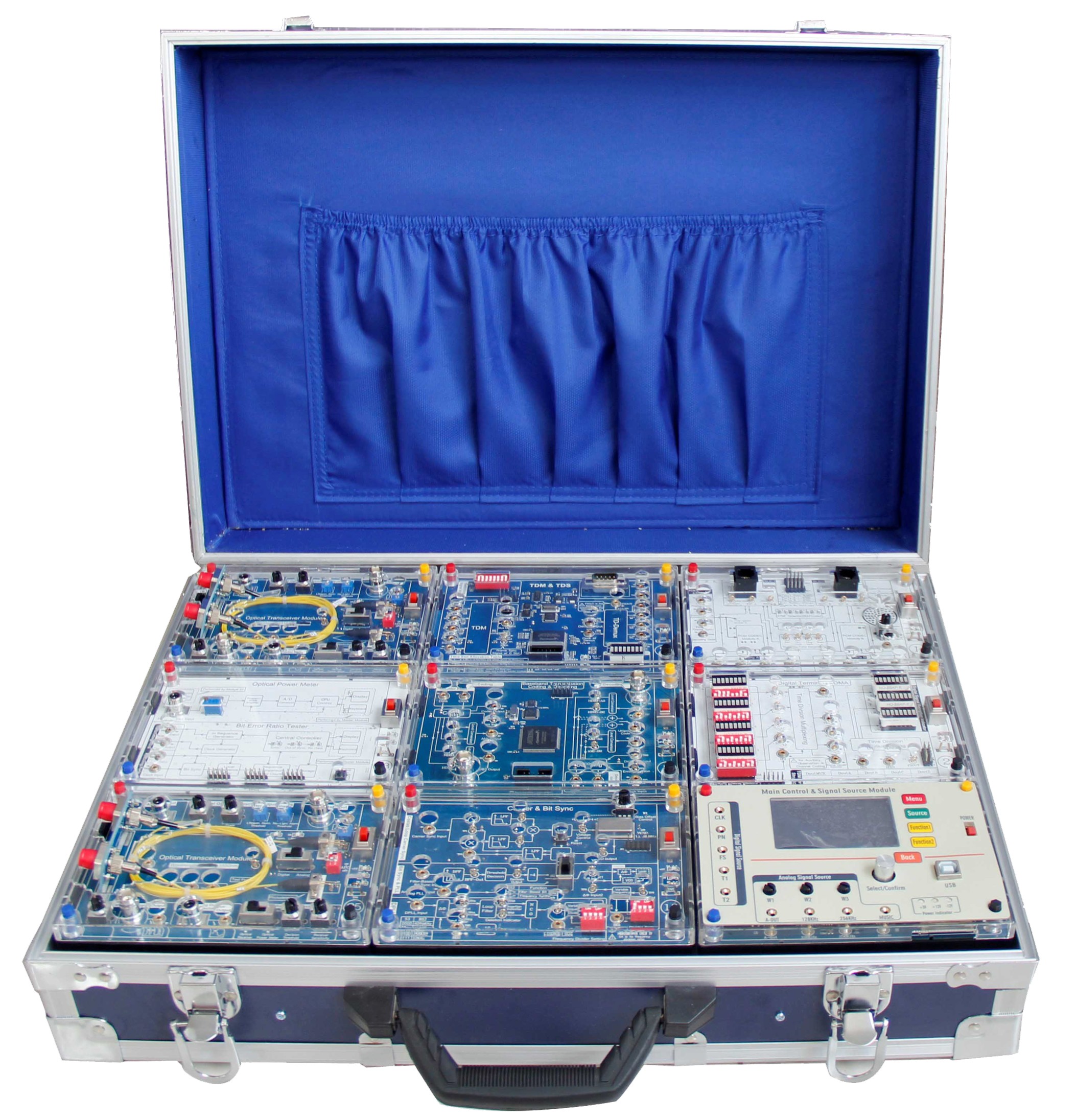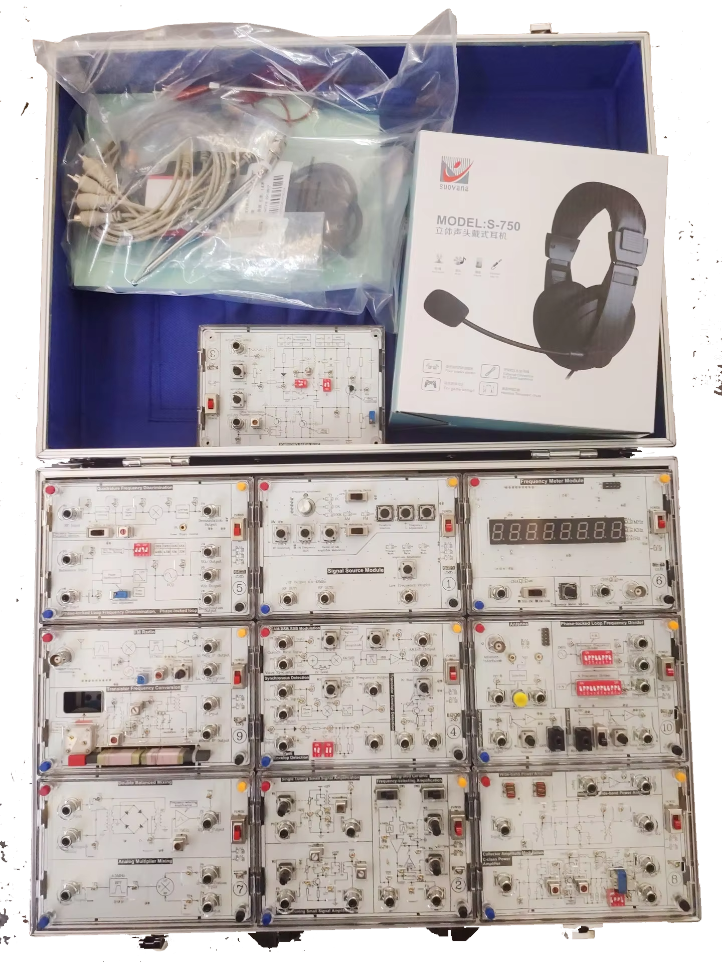
The Analog Communication Training System consist of below modules:
Specification:
Second Order Active Filters and RF Oscillators Module:
Second Order Active Low-pass, High-pass, Band-pass and Band-stop Filter.
Low-pass -3 dB frequency: 1 kHz ~ 3 kHz.
High-pass -3 dB frequency: 5 kHz ~ 10 kHz.
Center and Cutoff frequency: 10 kHz ~ 100 kHz and Bandwidth: 6 kHz ~ 60 kHz.
Colpitts Oscillator (Frequency: 1 MHz ~ 9 MHz).
Hartley Oscillator (Frequency: 500 kHz ~ 1.8 MHz).
Crystal Oscillator (Frequency: 6 MHz).
Voltage Controlled Oscillator (Frequency: 3.5 MHz ~ 4 MHz).
AM Modulator and Demodulator Module:
Transistor AM Modulator (Carrier Signal: 100 kHz ~ 500 kHz).
MC1496 AM Modulator (Carrier Signal: 500kHz ~ 1MHz and Audio Signal: 500 Hz ~ 1 kHz).
AM Diode Detector (Carrier Signal: 300 kHz, Audio Signal: 500 Hz ~ 2 kHz).
DSB-SC & SSB Modulator and Demodulator Module:
DSB-SC Modulator and Product Detector: (Carrier Signal: 100 kHz ~ 500 kHz).
SSB Modulator and Product Detector: (Carrier Signal: 200 kHz).
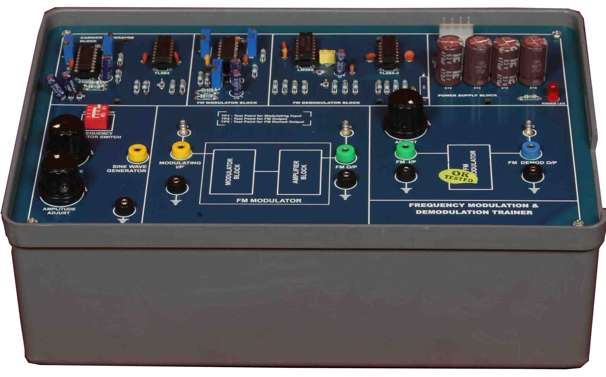
FM Modulator and Demodulator Module:
CD4046 and SN74124 FM Modulator: (Carrier Signal: 20 kHz).
LM565 and CD4046 FM Demodulator (Carrier Signal: 20 kHz).
TDM Multiplexer and De-multiplexer Module:
Waveform Generator (Sine wave: 13 kHz, Triangle and Square: 2.3 kHz).
TDM Multiplexer and De-multiplexer (Transmission: 3 Channels, Switching time: 500 ms ~ 50 ms).
FDM Multiplexer and De-multiplexer Module:
FDM Signal Generator (Carrier Signal: 100 kHz ~ 1.1 MHz).
DSB-SC Modulated Signal Generator: (Carrier Signal: 100 kHz ~ 1.1 MHz, Audio Signal: 500 Hz ~ 1.5 kHz).
FDM Multiplexer (Modulation: DSB-SC Signal, Transmission Bandwidth: 2 MHz).
FDM De-multiplexer (Modulation: DSB-SC Signal, De-multiplexing: Product De-multiplexer).
Analog-to-digital and Digital-to-analog Converter Module:
ADC0804 and ADC0809 Analog-to-digital Converter (Resolution: 8 bits, Analog Input Voltage: 0 V ~ 5 V).
R-2R Digital-to-analog Converter (Digital Input: 4 bits, Analog Output: 0 V ~ 5 V).
Unipolar DAC 0800 and Bipolar DAC 0800 Digital-to-analog Converter.
Frequency Converter and Signal Recovery Module:
Frequency Multiplier and Carrier Signal Recovery Circuit (Carrier Signal: 10 kHz)
Up/Down Frequency Converter and Clock Recovery Circuit
Function Generator and DC Power Supply Module:
Waveforms: Sine, Triangle, Square, TTL Pulse
Amplitude: >10 Vpp
Impedance: 50? ±10%
Duty Control: 30% ~ 60%
Display: 6-Digit LED Display
Frequency Range: 10Hz ~ 100 kHz (4 Ranges), 100Hz ~ 1 MHz (4 Ranges)
Frequency Control: Separative Coarse and Fine Tuning
Constant Voltage Output: ±5V, ±12V.
Variable Voltage Output: 0V ~ ±15V
Power source: 220~230V AC, 50Hz, 1 Phase
Standard accessories with printed operation manual.