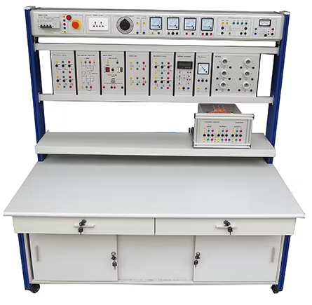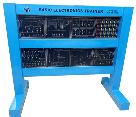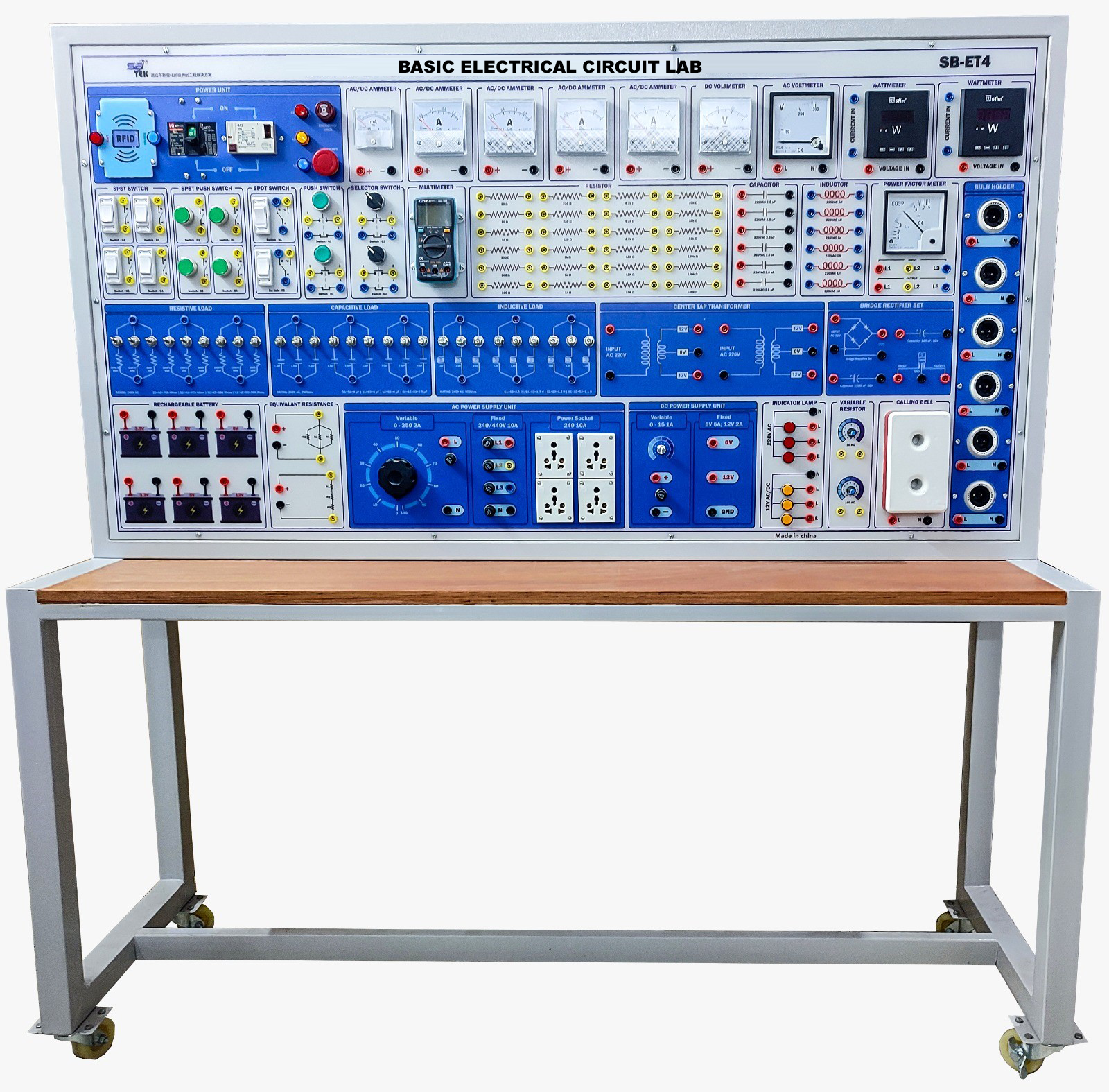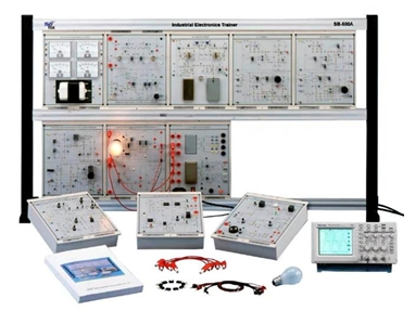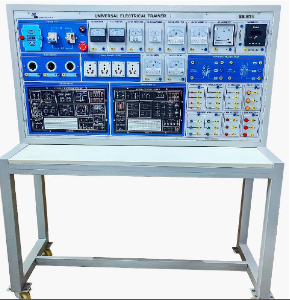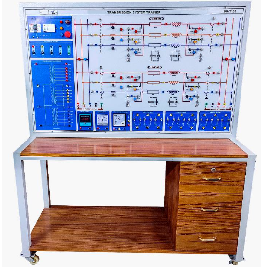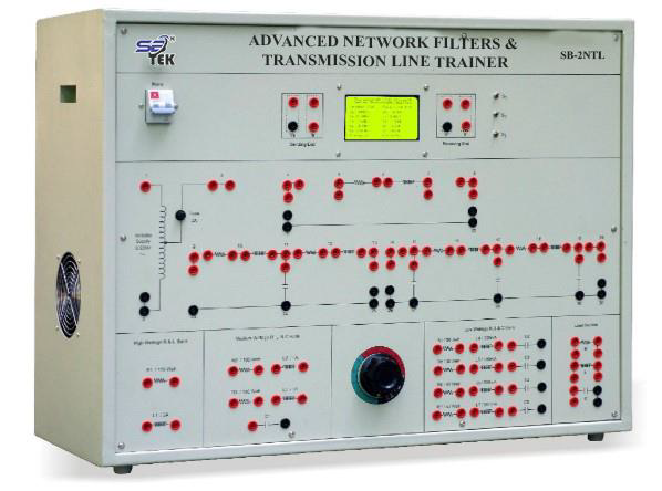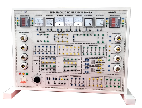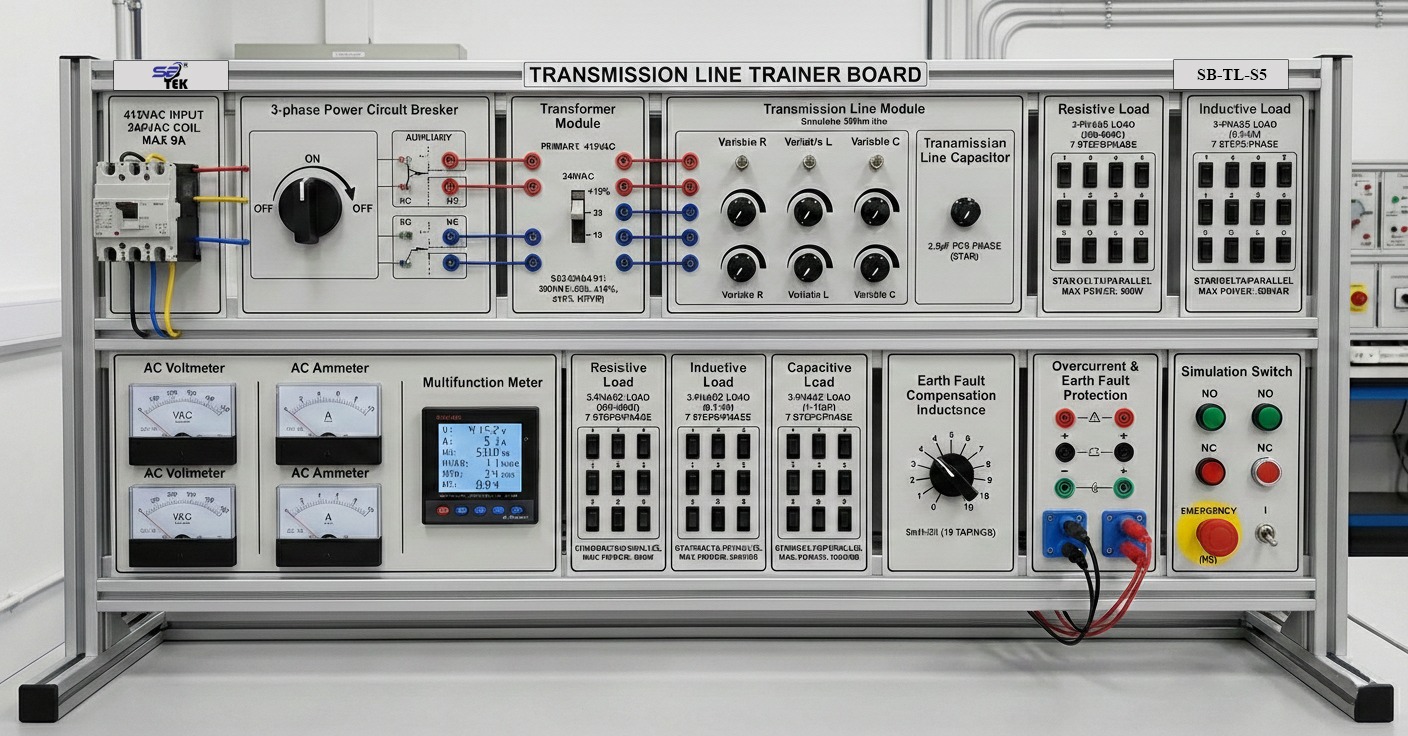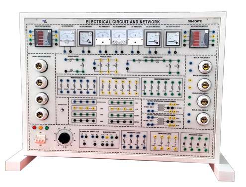
Description: The Electrical Circuit and Network Trainer is a versatile and comprehensive training system designed for engineering university labs to facilitate the study of electrical circuits and networks. It includes both AC and variable DC power sources with capabilities for single-phase and three-phase experiments, supporting a range of loads including resistive, inductive, and capacitive elements. The system enables the study of fundamental electrical laws and theorems such as Ohm's Law, Kirchhoff's Laws, and various circuit theorems, as well as the measurement of resonant frequency, Q-factor, and power factor of different circuit configurations. With its ability to simulate balanced and unbalanced loads in star and delta connections, this trainer provides hands-on experience in analyzing circuit behavior, enhancing students' practical understanding of complex electrical networks.
Specification:
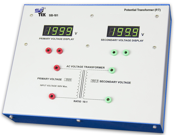
1. AC Power source for AC practical: Input voltage: 1? = 220V AC, 50Hz; 3 ? = 380 - 400V AC.
2. Output Capacity: Resistive Load: 220V, Capacity 1-? = 1000 W (min); 3- ? = 1000 W (min).
3. Resistive Load: 220V, 50Hz. 80Watt.
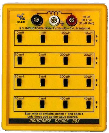
4. Inductive Load: 220V, 50 Hz. Capacity 1- ? = 120VAR-300VAR, 3- ? =350VAR (min).
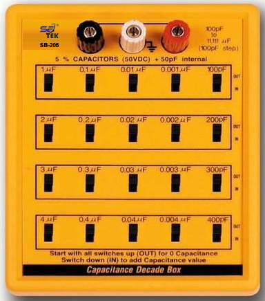
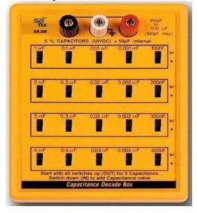
5. Capacitive Load: 220V, 50 Hz., Capacity 1- ? = 200VAR, 3- ? = 200 VAR (min).
6. Power factor of star and delta connected resistive, inductive, capacitive load and also 3? star connected load's neutral voltage, neutral current of balanced and unbalanced load.
7. Measuring resonant frequency, Q - factor of R-L-C series and parallel circuit.
8. Three phase supply indication.
9. Variable DC Power Source for DC Practical.
10. Three phase supply indication.
Expeiments:
1. Verification of Ohm's Law.
2. Study the characteristics of DC series, parallel, series-parallel or mixed circuit.
3. Kirchhoff's Voltage Law (KVL), Kirchhoff's Current Law (KCL), Thevenin's Theorem, Norton's Theorem, Superposition Theorem, Maximum Power Transfer Theorem, Reciprocity Theorem etc.
4. Study the characteristics of pure resistive, inductive, pure capacitive circuit as individual, series, parallel connected condition.
5. Measuring Effective resistance, current, voltage, active power, apparent power, reactive power, power factor, constructing vector diagram of pure resistive, inductive pure capacitive, R-L, R-C, R-L-C series circuit or parallel circuit.
6. Determining phase sequence of 3? EMF source and measuring 3? voltage, current, power,
7. Power factor of star and delta connected resistive, inductive, capacitive load and also 3? star connected load's neutral voltage, neutral current of balanced and unbalanced load.
8. Measuring resonant frequency, Q - factor of R-L-C series and parallel circuit.