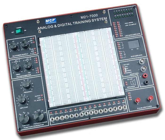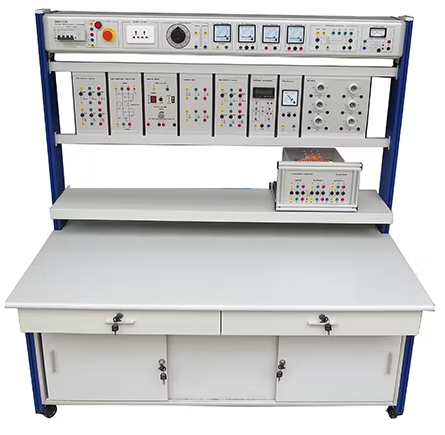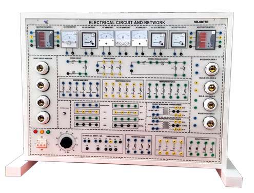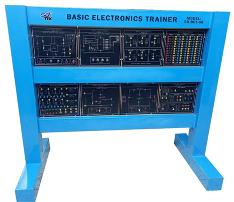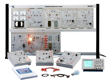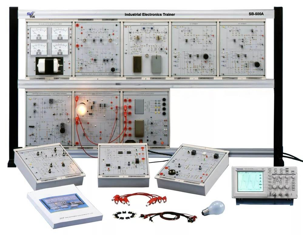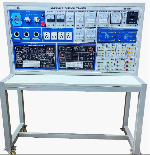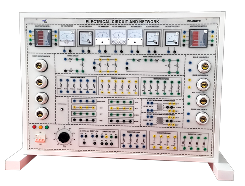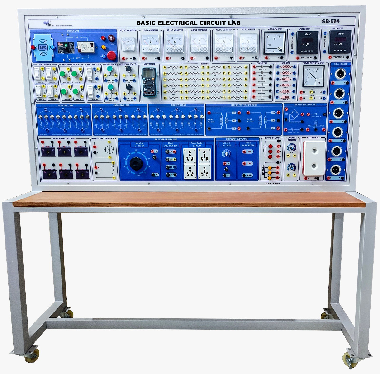
Description: Basic Electrical Circuit Lab is ideal for electrical, mechanical, automotive, science, civil & electronics engineering learning. All the necessary equipment for electric circuit experiments such as power supply, function generator; analog and digital meters are installed on the main unit for the requirement of experiment. The whole essential topics of electrical circuit learning are studied by different modules.
Technical Specification:
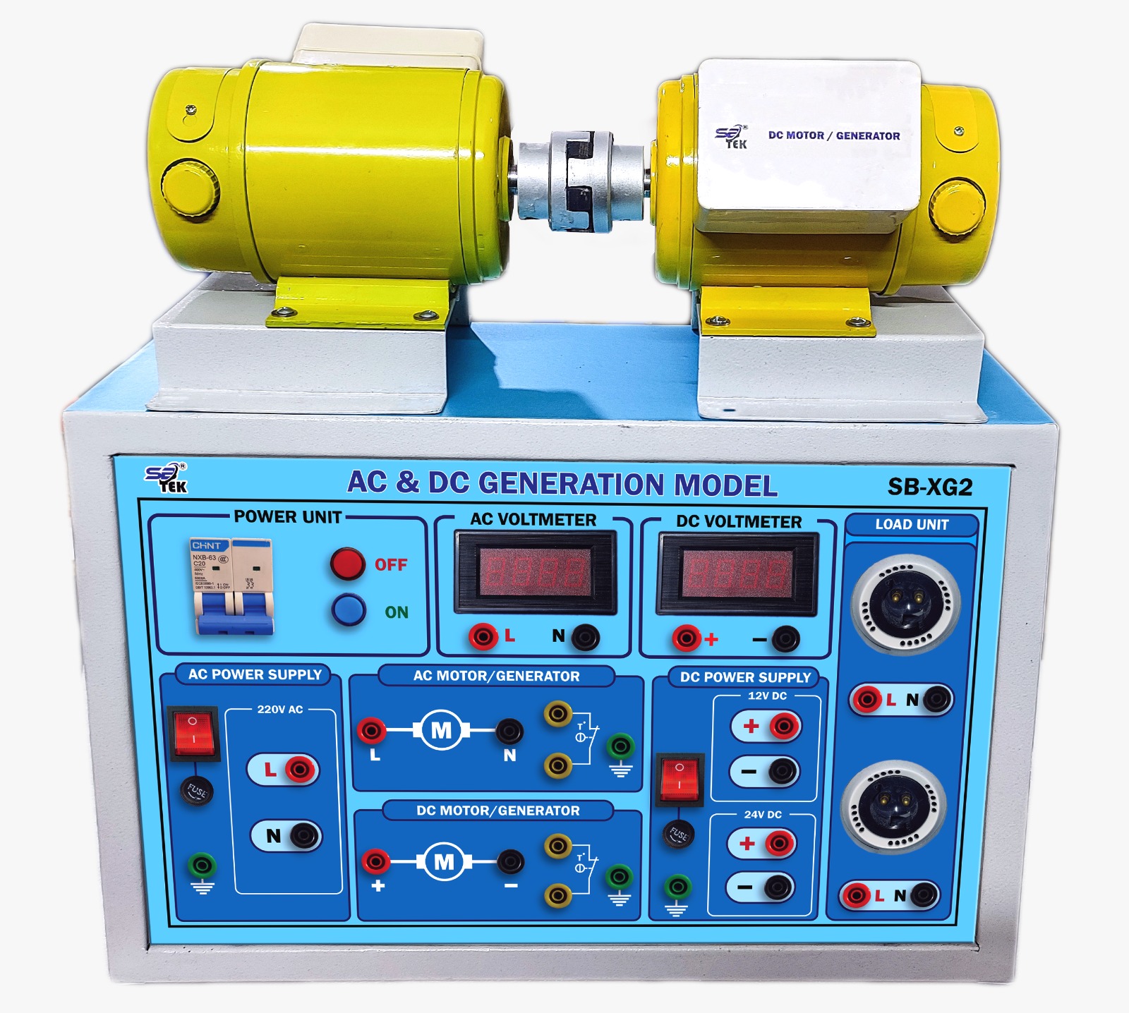
DC POWER SUPPLY:
1. Fixed DC power supply: Voltage range: +/-5V?+/-12V. Max. Current output: 0.3A. With output over-load protection.
2. Dual DC power supply: Voltage range?+/-3V~ +/-18V, continuously adjustable. Max. Current output: 1A. With output over-load protection.
AC POWER SUPPLY: Voltage range: 9V~0V~9V. Max. Current output: 500 m A. With output over-load protection.
SINGAL GENERATOR: Pulse generator: (TTL level). Frequency range: 1Hz~10KHz / 4 settings, continuously adjustable. Fan out: 10 TTL load. Pulse switches: 2 independent output, TTL level. With Q, Q output, pulse width > 5ms. Fan out: 10 TTL load
Data switches: 8 sets independent control output, TTL level with De-bounce circuit. Fan out: 10 TTL load
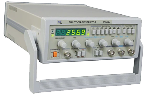
FUNCTION GENERATOR: Output waveform: Sine, triangle, square. Output frequency: 10~100KHz/4 settings, continuously adjustable. Output amplitude: 18Vpp (open circuit) 9Vpp (50 O load)
TESTING AND DISPLAY: 3 1/2 digital voltmeter/ammeter. DC voltage range: 2V, 200V. DC voltage accuracy: +/-(0.3% of reading +1 digit). DC current range: 200.
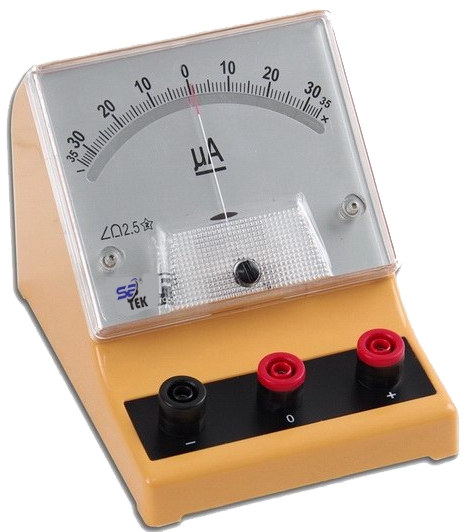
Galvanometer: Current range 50mA. Accuracy Class 2.5.
LED indicator: 10 sets independent LED indicates high, low logic state. Input impedance: ?100K?.
Digital display: 2 sets independent 7-segment LED. With BCD-7segment decoder/driver and DP Input. Input with 8-4-2-1 code
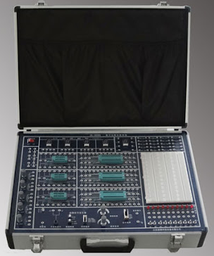
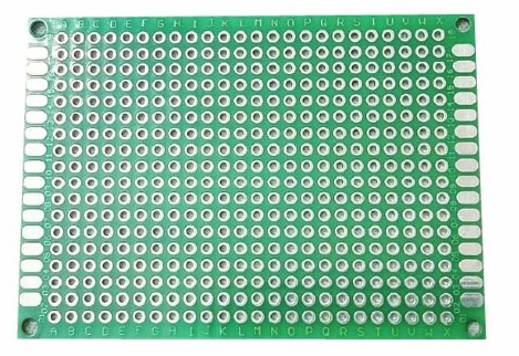
Breadboard: 1680 tie-point breadboard on top panel can be easily put into and taken off.
Accessories: Experiment manual, connection leads, connection plugs, breadboard
List of Module:
1. Basic Device Module.
2. Basic Electricity Experiment Module.
3. Sensor Module (1).
4. Sensor Module (2).
5. Diode, Clipper and Clamper Module.
6. Rectifier, Differentiator Integrator Circuit Module.
7. Transistor Amplifier Circuit Module.
8. Multi-Stage Amplifier Circuit Module.
9. FET Circuit Experiment Module.
10. OP Amplifier Circuit Module 1, 2, 3, 4, 5.
11. Combination Logic Circuit Experiment Module 1, 2, 3, 4, 5.
12. Sequential Logic Circuit Experiment Module 1, 2.
13. Load Unit Module
List of Experiments:
Basic Electricity Experiments
Basic electricity:
1. Resistor measurement.
2. DC voltage/current measurement.
3. Ohm’s law.
4. AC voltage/current measurement.
5. Series/parallel circuit.
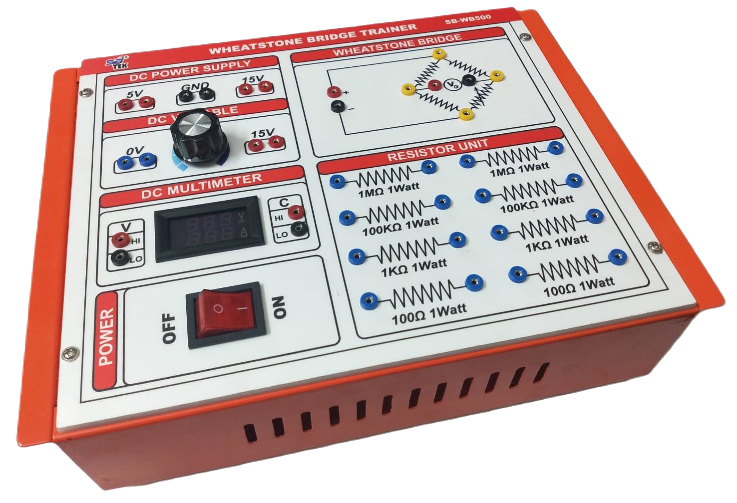
6. Wheatstone bridge.
7. Kirchoff’s law.
8. Thevenin’s theorem.
9. Norton’s theorem.
10. Maximum power transfer theorem.
11. DC RC and RL transient phenomena.
12. Power in DC circuit.
13. AC current/voltage experiment.
14. AC RLC series/parallel circuit.
15. Resonant circuit.
16. Power in AC circuit.
Control circuit:
1. Water level control.
2. Metal detector.
3. Light controller
Electronic Circuit Experiments
Diode experiments:
1. The Diode V-I characteristic curves.
2. The series diode clipping circuit.
3. The series diode clipping with bias circuit.
4. The parallel diode clipping circuit.
5. The parallel diode clipping with bias circuit.
6. The diode clamping circuit.
7. The diode clamping circuit with bias.
8. LED current characteristics.
9. Diode rectifier circuit.
10. Filter circuit.
11. Voltage multiplier.
Transistor experiment:
1. Measuring I,I,I and of PNP transistor.
2. Measuring I,I,I and of NPN transistor.
3. Transistor output characteristics curve EBC ? ?.
Transistor amplifier:
1. Fixed bias circuit.
2. Divide bias circuit.
3. Feedback bias circuit.
4. Common emitter transistor amplifier.
5. Common-collector transistor amplifier.
6. Common base transistor amplifier
Multistage amplifier:
1. RC-coupled amplifier.
2. Direct-coupled amplifier.
3. Transformer-coupled amplifier.
4. Push-pull amplification circuit
Darlington and FET circuit:
1. Darlington's circuit.
2. Field Effect Transistor (FET)type and characteristics.
3. JFET type and characteristics.
4. MOSFET type and characteristics.
5. Common source amplifier.
6. Common drain amplifier.
7. Common gate amplifier
OP amplifiers:
1. OP amplifier characteristics.
2. Non inverting amplifier.
3. Inverting amplifier.
4. Voltage follower circuit.
5. Adder circuit.
6. Differential amplifier.
7. Clipping circuit.
8. Constant-voltage circuit.
9. Constant-current circuit.
10. Differentiator circuit.
11. Integrator circuit.
12. Instrumentation amplifies.