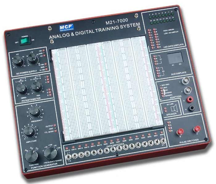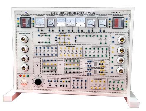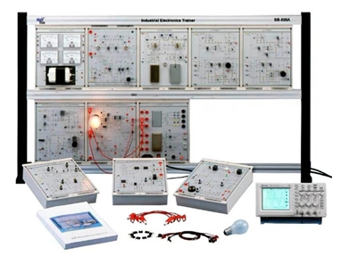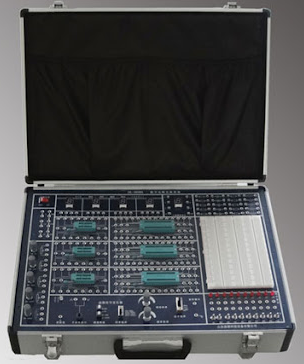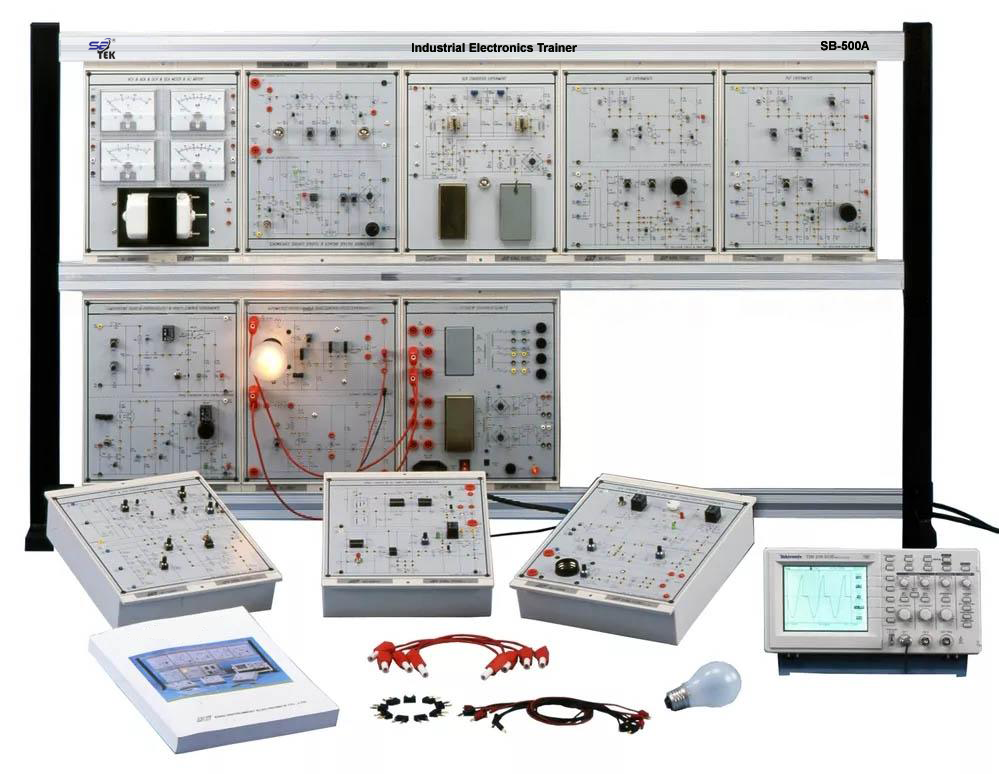
Features: This equipment should be all in one learning platform designed for smart engineering education. A total of 11 types of measuring instruments such as an oscilloscope, digital multimeter, DC power supply, AC power supply, and function generator are installed in the platform. Basic practices in various engineering fields are possible through the insertion of PCB type experimental modules onto the main unit. Bread Board Module is provided together, so it is possible to practice circuit configuration using actual electric and electronic components. The USB / Serial/ Ethernet communication environment enables interfacing with separate other devices and helps achieve the goal of differentiated smart education. A full color TFT LCD with touch screen provides clear screen view and convenient user interface. The built-in integrated measurement board is equipped with a 3 CORE CPU to enable fast and powerful computational performance. The eBooks capable of smart learning can be displaye
conversion, vector control, automobile and electric vehicle, and automation system.
Technical Specifications:
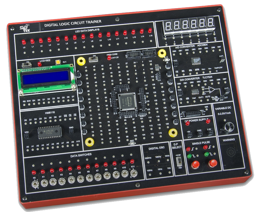
1. Platform (Advanced): Embedded OS based smart learning platform; Intel® CPU Atom? Processor-1.6GHz, 800MHz FSB, 512KB L2 cache; 2.1W ultra low power system, FCBGA package; Hyper threading and 45nm technologies; Ethernet, USB and Serial interface; Touch screen resolution: 800 x 480; 124point connector to connect an experimental module; Integrated measurement board employing the 3core CPU; Installed measurement application software (OS: Microsoft Embedded); Multilingual selection and smart touch user interface control; Audio and video control functions.
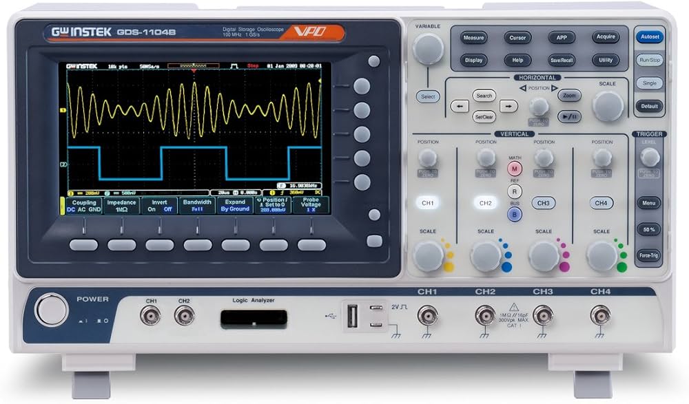
2. Signal input (2channel) Oscilloscope:
Impedance: 1M?/20pF: Max voltage: ±50Vpp; Bandwidth: 4MHz; Sample rate: 40MS/sec; ADC resolution: > 10bit; Voltage DIV: ±10/5/2/1/0.5/0.2/0.1/50mV/20mV; Time DIV: > 22 times 1us~10s; Trigger: Auto, Single,
Stop Mode; Memory: Streaming to host
Voltmeter & Ampere meter.
Measurement: AC/DC voltage, current, power(VA); Function: Mean value, Peak value, Peak to Peak value, Root mean square (RMS) value; Range: Auto & Manual Mode ( > 9step 100mV~50V).
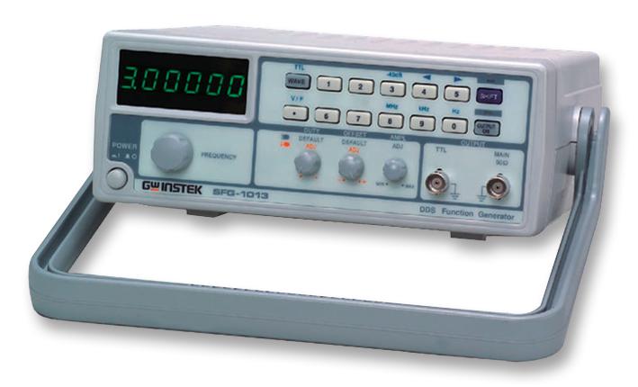
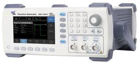
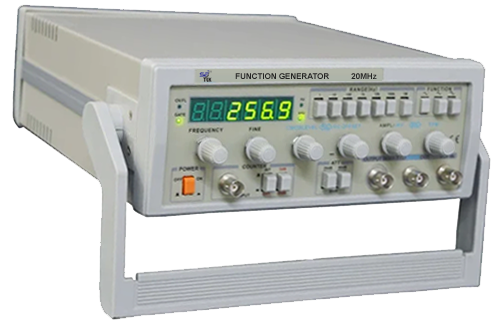
3. Signal output (1channel) Function / Pulse / Arbitrary Generator.
Impedance: 50?/200mA; Amplitude: 200mVpp, 2Vpp, 20Vpp (Max. 20Vpp); Frequency: 0.1Hz 1MHz; Range: 0.1Hz/1Hz/10Hz/100Hz/1kHz/10kHz/100kHz (7step); Output waveform: Sine, Square, Triangle, Logic, DC Pos(+), DC Neg(). DC Source
Range: 100mV, 1V, 10V; Voltage Source: ±0 ~ 10V. Digital input (digital analyzer / counter)
Number of channel: 16 (Int. +Ext.); Input voltage: TTL/CMOS; Max. voltage: 20V; Frequency: 100kHz; Trigger mode: Low, high, DC; Memory: Streaming to host; Function: BIN (2bit), OCT (8bit), DEC (10bit), HEX (16bit)
Digital output (Signal generator / timer)
Number of channel: 16 (Int. +Ext.); Output voltage: TTL/CMOS; Output current: 3mA; Max. voltage: ±15V; Output frequency: 100kHz; Memory: Streaming to host; Function: BIN (2bit), OCT (8bit), DEC (10bit), HEX (16bit)
Relay output: 8relay COM; NO/NC (Normally Open/Closed); 24VDC / 1A.
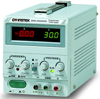
4. Variable power supply 3channel DC power
V1 voltage: DC 0 ~ ± 20V 1A; V2 voltage: DC 0 ~ ± 20V 1A; V3 voltage: DC 0 ~ ± 20V 1A
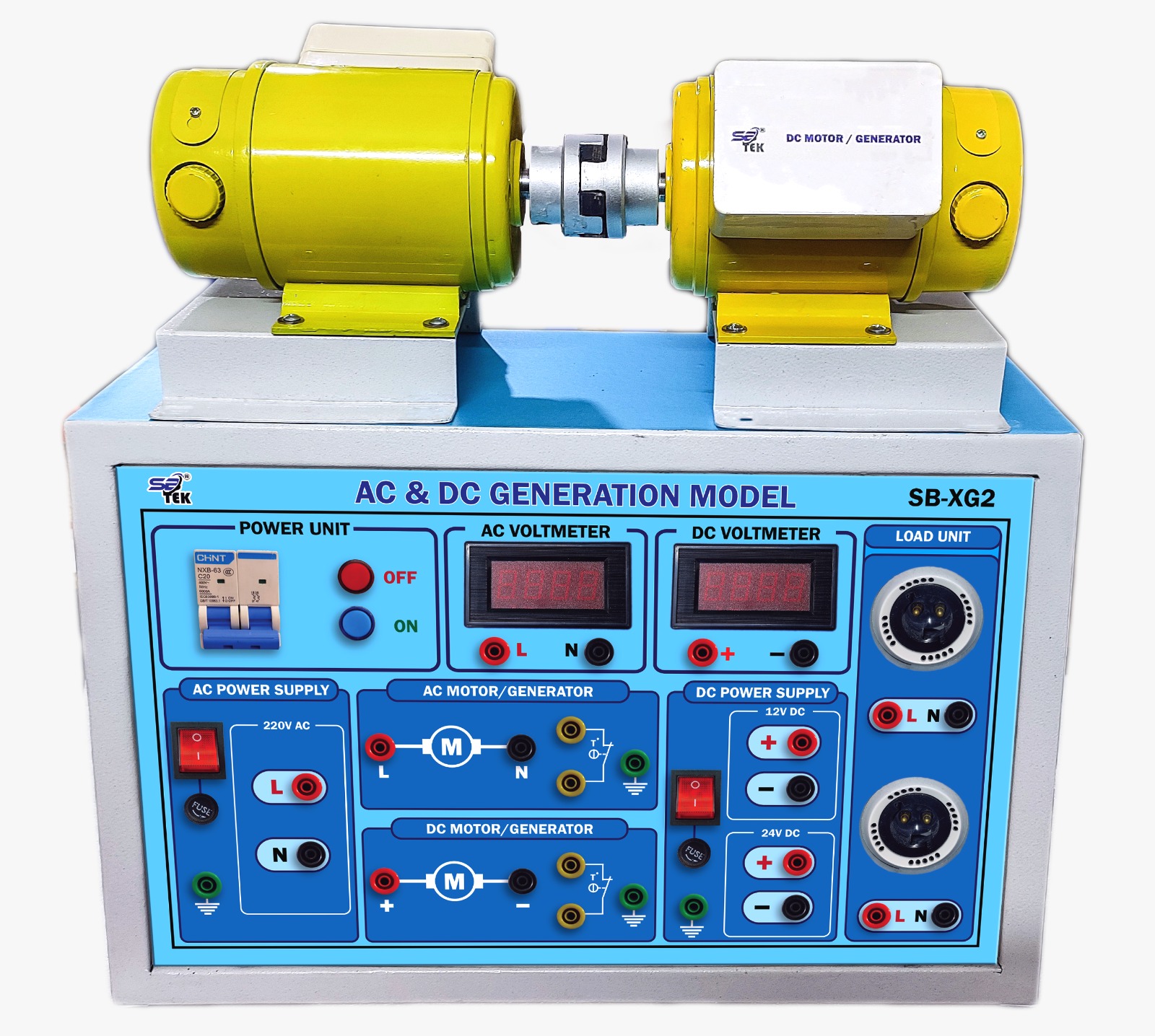
5. 3phase AC power AC voltage: AC 14Vrms 1A (Resolution: 0.1V); Frequency: 1Hz ~ 150Hz (Resolution: 1Hz).
6. Advanced 3phase power: Function: Sine, V Sine, Block, Pulse; V1 voltage: AC 0 ~ 100%; V2 voltage: AC 0 ~ 100%; V3 voltage: AC 0 ~ 100%; V2, V3 phase shift: 0 ~ 359°; Frequency: 1 ~ 150Hz; Clock frequency: 10kHz ~ 32kHz
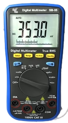
7. Digital Multimeter: Voltage: DC 1V, 10V, 100V, AUTO. AC 700mV, 7V, 70Vrms, AUTO, 40Hz ~ 20kHz; Current: DC 500mA, 2A, AUTO;
AC 500mA, 2Arms, AUTO, 40Hz ~ 5kHz; Resistance: 100?,1k?,10k?,100k?,1M?,10M?, AUTO; Capacitance: 10?,100?,1?,10?,100
?,1000?, AUTO; Continuity diode: 1V, 10V
Fixed power supply: Fixed voltage: +3.3V/2A, +5V/2A, ±15V/500mA (Common)
Application software for measurement (installed in the main unit)
1) Measurement control
All functions are directly connected to the equipment to control and to set up I/O values identical to actual instrumentation devices. Oscilloscope: By setting the signal (voltage) value according to the time setting (22 values between 1us and 10s per time unit), you can display a waveform graph for each of the two channels, Channel A (yellow) and Channel B (blue), and compare waveforms. It provides XY (Lissajous' figure) and trigger functions. Power meter: Calculation of wattage (voltage x current) is possible through the voltage input to channel A and current of channel B. Voltage & Ampere meter: You can select a measurement mode to measure voltage or current in two channels, and can measure current through a virtual resistance input. There are five measurement modes: AV, |AV|, P, PP, and RMS. Function generator: It provides the function of selecting basic output signals [sine/square/ triangle /logic/DC (+)/DC ()]. The user can configure a setting display window showing the setting status and the voltage output level and frequency. Pulse generator: The setting display window, voltage output level and frequency can be configured. It provides the function of controlling and adjusting the pulse output signal (unipolar/ bipolar/short pulse) and pulse width. Arbitrary waveform generator: It provides basic waveforms such as sine wave, triangle wave, and square wave provided by the function generator. It also offers various types of other waveforms suitable for laboratory experiments (All Sine, Half Sine, Sin(X)/X, Cosine, Tangent, Up Ramp, Down Ramp, Up Stair, Down Stair, and Noise). DC source: DC voltage can be generated in the range from 10V to +10V. The range selection helps increase accuracy at the time of setting up the voltage. Digital multimeter: The user can select a range for measuring DCV (DC voltage), ACV (AC voltage), DCI (DC current), ACI (AC current), short circuit resistance (Beep), resistance, capacitance, diode measurement.
3channel DC power supply: Each channel of V1,
V2 and V3 makes an output of DC voltage from 20V to 0V to +20V. (In case of short circuit in the output terminal or overload in the circuit of a particular experiment, the alarm goes off and the output of the power supply will be cut off for circuit protection.)
3phase AC power: The output voltages and output frequencies of V1, V2, and V3 output terminals are simultaneously varied. The accuracy of the output voltage is 0.1V, and the outputs of V1, V2, and V3 can be used for the Y/? type AC power circuit. Advanced 3phase AC power: The 3phase AC power (V1 ~ V3) can be adjusted as a percentage, and make a variable output. The phase shift of V2 and V3 is 0 ~ 359°, the clock frequency is 10 ~ 32kHz, and the frequency is 1 ~ 150Hz. It provides an arbitrary setting output function and an output waveform display function.
Digital input: The digital input data are displayed up to 16 bits on the touch screen and can be switched to four types of numeral system (2/8/10/16).
Digital output: The digital output data are displayed up to 16 bits on the touch screen and can be switched to four types of numeral system (2/8/10/16).
Relay: Eight relays can be individually controlled, and the status of N.C (Normally Close) and N.O (Normally Open) are displayed.
2) Ebook function Format: HTML
The composition is the same as the experimental manual. The electronic circuit practice consists of 16 chapters whereas the electric circuit practice consists of 11 chapters.
It enables quick selection and movement of the practice tasks as well as table of contents for each section.
Flash design for circuit connection enables learning in more details.
The circuit diagram of experimental modules can be enlarged or reduced in the HTML document by scrolling the mouse.
11) Circuit design and simulation software (Should be installed in the main unit) C language design (built in compiler); Realtime control and measurement. Circuit design and simulation applications
Power electronic circuits, electronic circuits, Power source or signal source design, Power system, Mechanical load, Renewable energy circuits, Electrical drive circuits, Digital logic circuits, Control circuits, Electrical system, Mechatronics system
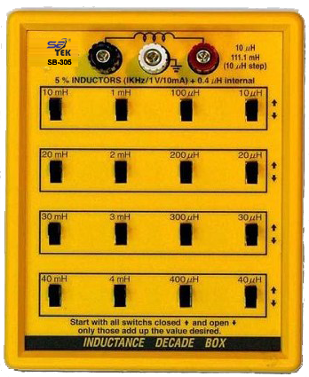
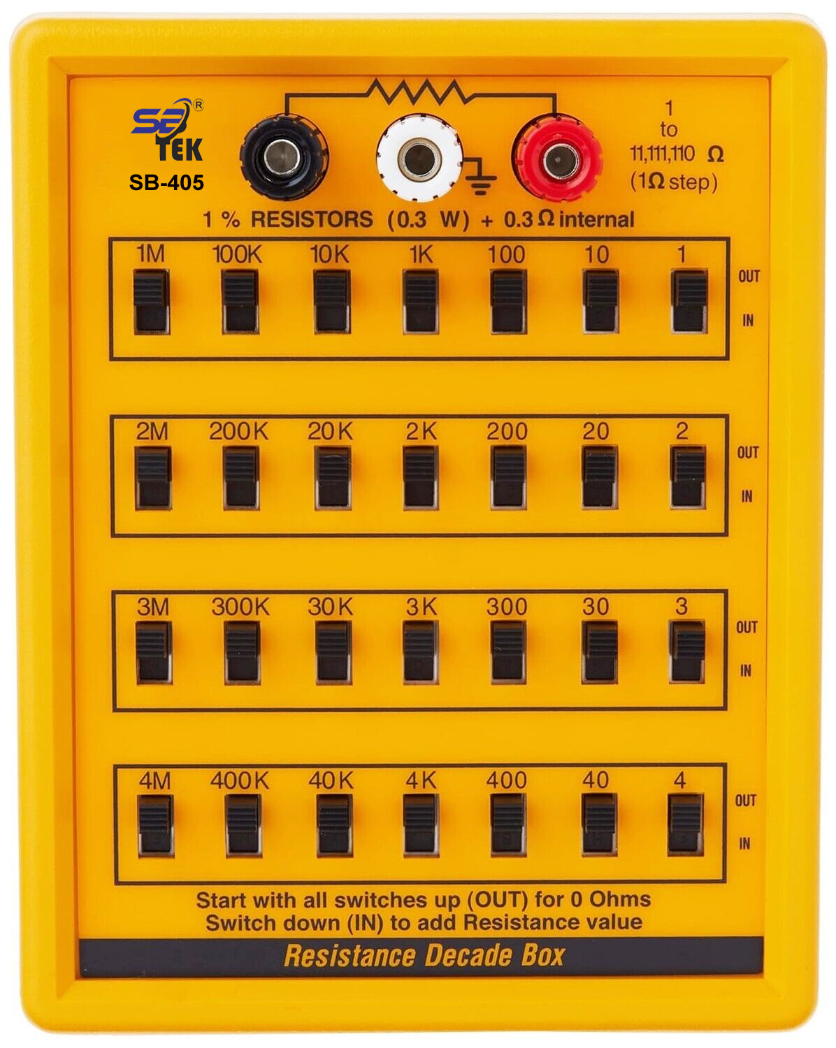
Electricity Module Package for Smart Lab
Basic Electricity Package: RLC circuit, Ohm's law, Kirchhoff's law, Superposition theorem, Norton's theorem, Thevenin's theorem, AC/DC voltage measurement, AC/DC current measurement, AC/DC power measurement, AC circuit (RC/RL/RLC), DC circuit (RC) and transient phenomenon, Series parallel combination logic
Electromagnet: Basic principles of electromagnet, Characteristic of magnetic field, Characteristics of magnetic system, Switch and relay practices using a magnet
Electromagnetic field
Principles of electromagnetic field Lenz Law, Faraday Law, Strength of the magnetic field, Drawing magnetic lines
Characteristics of magnetic field, Electromagnetism Ampere's Law, Direction of magnetic field, Flow of current.
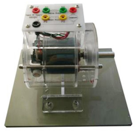
Fleming's Law: Motor and generator, Fleming's Law. Characteristics of coil Magnetic induction Mutual induction Magnetic flux detection
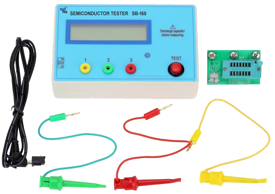
Basic semiconductor circuit: Characteristics of Diode and Zener diode, Rectifier circuit, Filter circuit, FET/SCR/UJT characteristics, Principles of LED. Basic electrical circuit Amplifier, Multistage amplifier, Cascade amplifier, Constant voltage circuit, Relay and touch control switch.
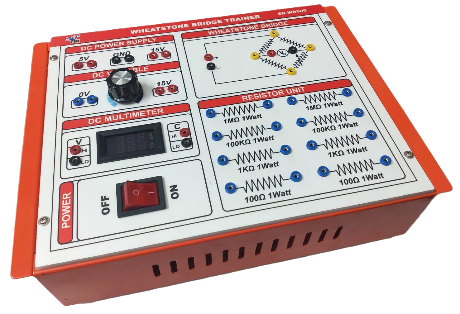
Electroacoustic amplifier circuit: Push pull amplifier, Whetstone bridge, Sound control circuit.
Characteristics of electrical elements: CDS characteristics, Light control switch, Principles of thermistor, Temperature control circuit
Oscillator circuit: Blocking generator, electronic bird sound generator, A stable multi vibrator, LC resonant circuit, LED flashing circuit.
Following Power Electronics and Electrical Simulation.