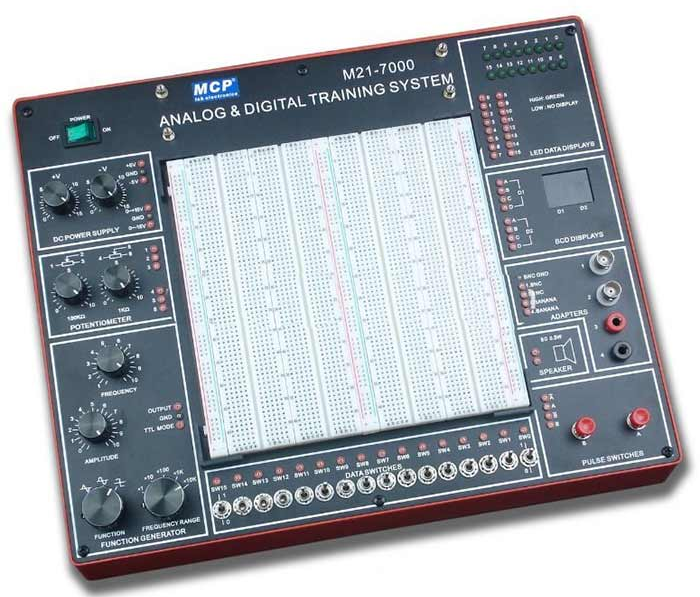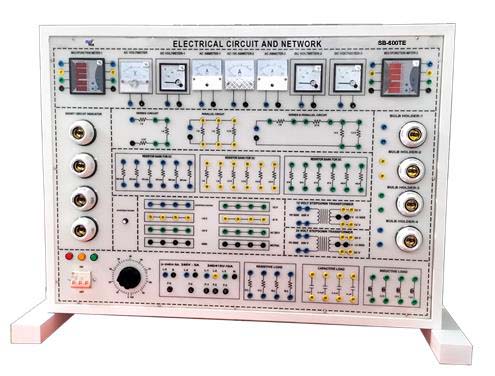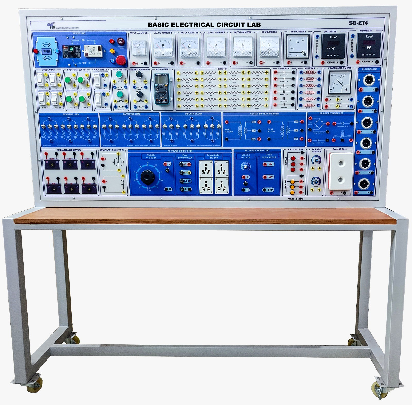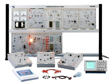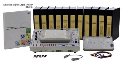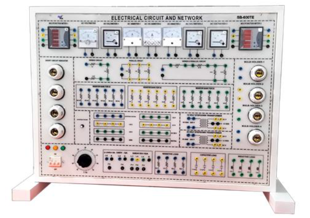
Features: Built-in basic measuring equipment Available to study an electric, electronic, communications and digital logic circuit themes with one platform Providing simulation proven training circuits. Training skills for troubleshooting. Shutdown circuit configuration for equipment protection. Module set based on verified circuit. Application experiments available through built-in bread board and universal board. 2.8inch Color LCD. Built-in high-performance oscilloscope. It consists of measuring equipment such as oscilloscope (Using PC Software), waveform generator, multimeter, and various input/output devices that can be used for experiments of analog and digital circuits. Basic experiments can be done intuitively by constructing basic electric and electronic circuits into modules for practical exercises. By using AC power, Variable DC Power, Fixed Power, Variable Resistor and Analog and Digital Switch, the circuit of bread board can be configured to use Speaker, FND, LED, etc. 2 ch
Specifications:
Hardware Specifications:
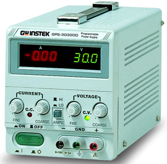
Input Parts: AC Power: 0VAC, 3VAC, 6VAC, 9VAC, 12VAC; 3-digit 7Segment Display (Selected AC Power). Variable DC Power1: +1.5V ~ +18.5V; 3-digit 7Segment Display (Output DC Power). Variable DC Power2: 1.5V ~ 18.5V; 3 digit 7Segment Display (Output DC Power) Analog Signal: +5V ~ 5V. Fixed Power (DC): +20V, +15V, +5V, GND, 5V, 15V. Slide Switch: +15V/0V Switch 2EA; +5V/0V Switch 2EA; 5V/0V Switch 2EA; 15V/0V Switch 2EA
Button Switch: +15V/0V Switch 1EA; +5V/0V Switch 1EA; 5V/0V Switch 1EA; 15V/0V Switch 1EA
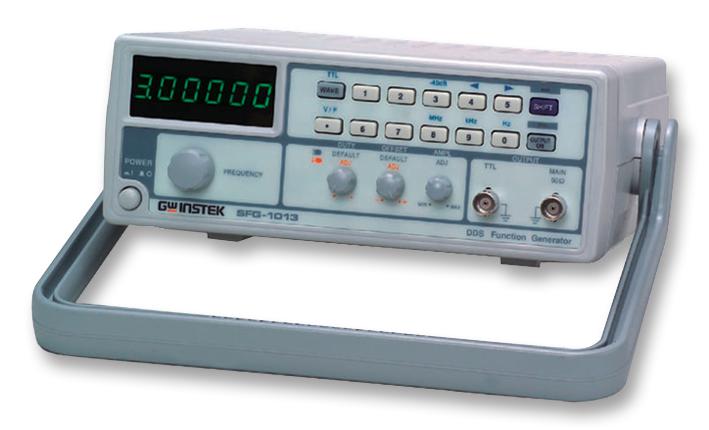
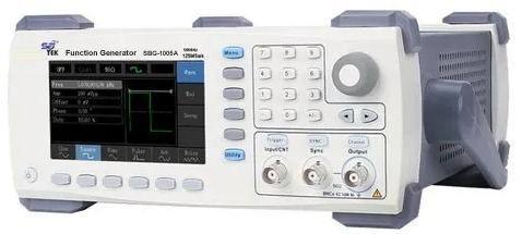
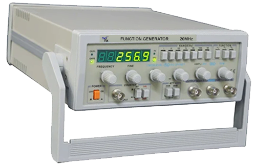
Function Generator: Waveform: Sine/Triangle/Square DC Offset: 5V~+5V. Amplitude: 0V~10Vpp. Frequency: 0 ~ 1kHz, 1kHz ~ 10kHz, 10kHz ~ 100kHz Duty Rate: 10~90% (Square). Output Level: +5V TTL Level
Fixed Frequency: Output Level: +5V TTL Level; Frequency: 0.5Hz, 1Hz, 50Hz, 100Hz, 500Hz, 1kHz, 5kHz, 10kHz.
Variable Resistor: 1k?-1EA, 5k?-1EA, 10k?-1EA, 50k?-1EA.
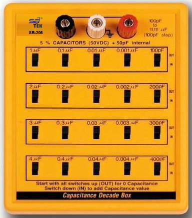
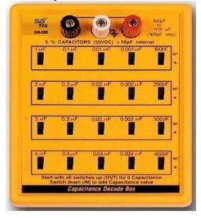
Select Capacitor: 100pF, 1nF, 10nF, 47nF, 100nF, 1uF.
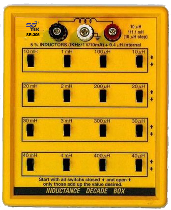
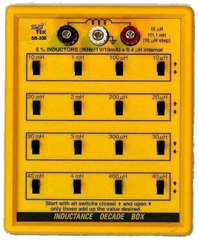
Select Inductor: 47uH, 100uH, 220uH, 470uH, 1mH, 2.2mH.
Output Parts: LED display: 5pi RED LED 8EA.
7Segment Display: Anode Common 7Segment 1EA;
Cathode Common 7Segment 1EA
Speaker: 4? Speaker with Volume Control Measurement Parts:
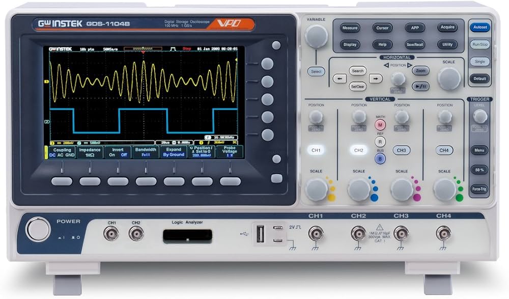
Oscilloscope: Using PC Software (USB Cable connected). Display: 2.8inch 64K Color TFT LCD, 320x240 Pixels Resolution Sampling Speed: 250MHz (single ch),125MHz (dual ch)
Band Width: 70Msps/ch Measurement Range: 30V~+30V Voltage Division: 10mV~10V. Record Length: Max 6K samples for single channel; 3K samples per dual channel SEC/DIV Range: 5ns/div~500s/div 1, 2, 5 sequence
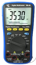
DC Gain Accuracy: +3% for Normal or Average acquisition mode, 10V/div to 10Mv/div Multimeter: Maximum Resolution: 4000 Counts AC/DC Voltage: Up to 600V AC/DC Current: Up to 10A Resistance: Up to 40M? Capacitance: Up to 100Uf. Diode: 0~1V. Testing Modes: Voltage, Current, Resistance, Diode, Capacitance Measurement Block: Display: 3-digit 7Segment display. Measure Select: Voltage/Ampere/Frequency Voltage measure: 0~30V. Ampere measure: 0~9.99A Frequency measure: 0Hz~5MHz. Display unit using LED
DAQ: Using PC Software (USB Cable connected) Sampling Speed: 1ms, 10ms, 100ms 1s Input: 8bit digital Data. Output: 8bit TTL Level. Waveform Generator: A/D Convertor with 8bit output data Theme Module Block:
Electronic Theme Block: Power: +20V, +15V, +10V, +5V, GND, 5V, 15V. Size: 172 mm x 110mm or 200mm x 110mm 2EA. Communication Theme Block: Power: +15V, +5V, GND, 5V, 15V. Size: 250mm x 200mm 1EA
Digital Logic Theme Block: Power: +5V, GND. Size: 70mm x 50mm 4EA. Using Adaptor Module in Electronic Thema Block Over Current Check Block: Power Protection Circuit:
If the circuit uses more than the allowable current for short-circuit reasons, shutoff the power. When the temperature inside the equipment is over a certain temperature (70?), the power is cut off. Beep sound when power off. LED indicates the location of the power source that is problematic when the power is off. LED informs the status of power connection/operation/short Power can be switched on/off using a switch.
List of Experiment:
Module 1: Ohm's Law: Series, parallel, series parallel circuit of resistance.
Module 2: Kirchhoff's Law: Kirchhoff's Law of Voltage Kirchhoff's Law of Current.
Module 3: Law of Distribution: Law of Voltage Distribution.
Module 4: Maximum Power Delivery: Maximum Power Delivery Conditions
Module 5: Thevenin and Norton's Theorem: Thevenin's Theorem, Norton's Theorem
Module 6: Principle of Superposition: Understanding circuit analysis method when there are two or more current and voltage sources.
Module 7: Loop, Node Method: Understanding loop and node equations with independent voltage and current sources.
Module 8: RC Series, Parallel Circuit: Understanding Current Voltage Characteristics of RC Series Circuits Understanding Current Voltage Characteristics of RC Parallel Circuits.
Module 9: RL Series, Parallel Circuit: Understanding current voltage characteristics of RL series circuits Understanding current voltage characteristics of RL series circuits.
Module 10: RLC Series, Parallel Circuit: Understanding RLC Series and Parallel Circuits in AC. Understanding the resonance characteristics of RLC series and parallel circuits.
Module 11: Diode: Understanding how diodes work. Understand voltage current characteristics of diodes Understanding the Voltage Current Characteristics of Zener Diodes.
Module 12: Clipper, Clamper: Understand the operation of series and parallel clippers and biased clippers. Understanding clamper circuits according to diode direction.
Module 13: Rectifier Circuit: Understanding of Halfwave, Full wave, Bridge Full wave Rectifier.
Module 14: Filter: Understanding circuits of Low Pass and High Pass Filters. Understanding circuits of Band Pass and Band Stop Filters.