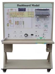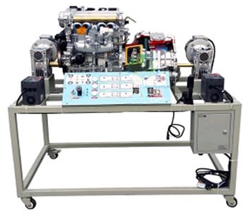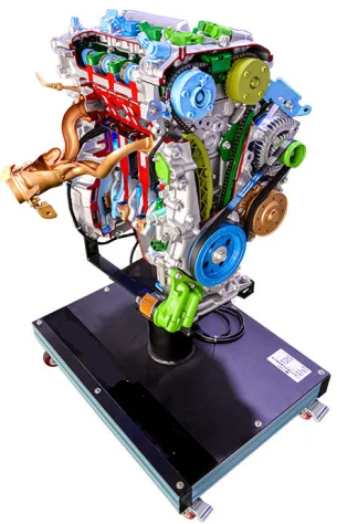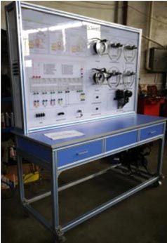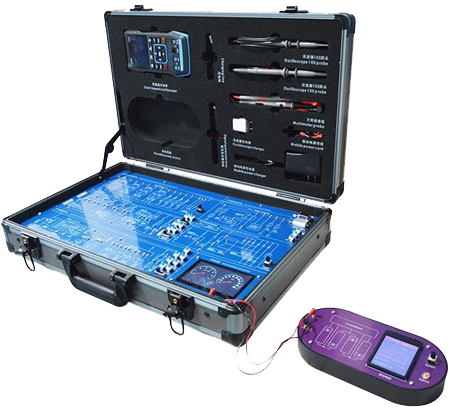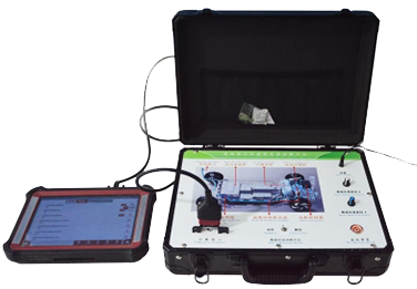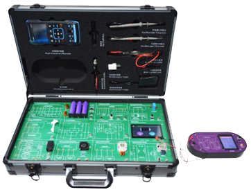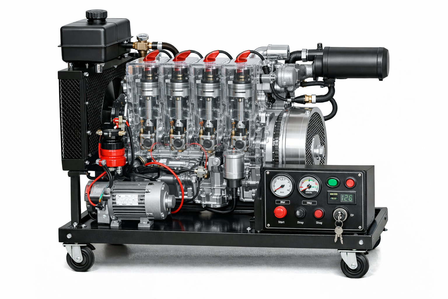
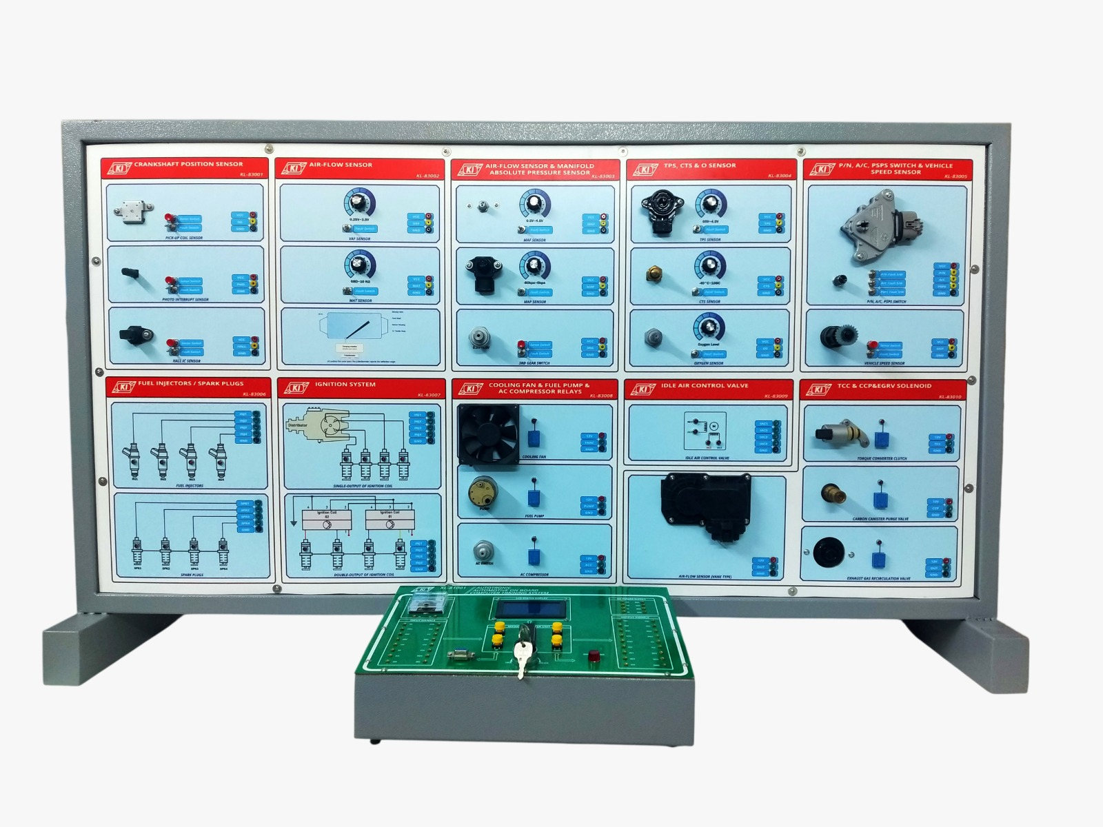
01. SYSTEM OVERVIEW The SB-AT08 is an interactive, computerized automotive training system from SB-TEK. It is modularized for electronic and automotive courses, letting students simulate fuel injection, ignition, and exhaust gas control systems on real automotive circuitry rather than a simplified mock-up. All learning is supported by PC-based supervision and dedicated software (laptop/notebook not included). The system pairs a single-chip microcontroller-based main unit with ten plug-in experiment modules, an integrated TFT display for on-unit process visualization and control, and a built-in web server for remote monitoring, data logging, and trend analysis — giving students a complete path from live sensor measurement to networked data review.
02. CORE HARDWARE SPECIFICATIONS
Parameter Specification
Power Supply Fixed DC output, +5V & ±12V; +5V/2A, +12V/2A max current; overload protection
Computer Interface RS-232C, 9-pin D-sub connector
CPU Single-chip microcontroller
Display (Base LCD) LCD graphic display: 64×128, with backlight; synchronously displays NE/PHO/HALL, MAF, MAT, MAP, TPS, CTS, VSS, IPW; analog oxygen meter
Selectors Select: NE, PHO, HALL; Mode: Fuel injector selects (Sync / Non-sync / Sequence)
Input Signals NE, PHO, HALL, VAF, MAT, F/C, MAF, MAP, TPS, CTS, O2, P/N, A/C, PSPS, VSS, 3GR
Output Signals INJ1–4, SPK1–4, FANC, F/C, ACC, IAC1–4, TCC, CCP, EGRV; Check engine lamp
Display & Control Panel TFT display showing real-time temperature/parameter readings for all monitored segments; provides full on-unit control of the entire process
Remote Monitoring (Web Server) Built-in web server for remote monitoring via browser — live process data, automatic data logging, and temperature/parameter trend graphing
Network Connectivity Ethernet / Wi-Fi interface for LAN access to the web-based monitoring dashboard from any connected PC or mobile device
Data Export On-board data logging with exportable history records (CSV) for post-lab analysis and report writing
Alarm & Threshold Indication Configurable high/low alarm thresholds with on-screen and web-dashboard indication for out-of-range readings
03. KEY FEATURES
• Single-chip microcontroller-based computer interface and monitor control
• Fuel injection, ignition, and exhaust gas data acquired and monitored by computer
• Can be assembled as a full injection system
• Trouble-shooting simulation function
• Switch-off input/output function during trouble-shooting
• Integrated TFT display for real-time process visualization and full on-unit control
• Web-based remote monitoring with automatic data logging and temperature/parameter trend graphs
• Network-ready (Ethernet/Wi-Fi) for classroom-wide dashboard access from multiple devices
• Exportable data logs for post-experiment analysis and lab reporting
• Configurable alarm thresholds for out-of-range parameter alerts
04. EXPERIMENT MODULES
The SB-AT08 ships with ten dedicated plug-in experiment modules, each housing the circuitry for a specific automotive sensor or actuator subsystem:
Module Code Key Specs
Crankshaft Position Sensor SB-AT08-M01 Pick-up coil, photo interrupt, Hall IC sensors
Air-Flow Sensor (Vane Type) SB-AT08-M02 VAF: 0.25–3.5V; MAT: 68?–10K?; F/C fan control switch
Air-Flow Sensor (Hot Wire) & MAP Sensor SB-AT08-M03 MAF: 0.5–4.5V; MAP: 1.2–3.6V (-80kPa~0kPa)
TPS, CTS & O2 Sensor SB-AT08-M04 TPS: 0.5–4.5V; CTS: 4.5V/-40°C, 2.3V/20°C, 0.5V/108°C; O2 normal/rich/lean swings
P/N, A/C, PSPS Switch & VSS SB-AT08-M05 Park-neutral, A/C, power steering pressure switches; speed-adjustable VSS + 3GR switch
Fuel Injectors/Spark Plugs SB-AT08-M06 Injector static load 18?, 800–3600rpm, sequence changeable, LED displays
Ignition System SB-AT08-M07 Single-output coil (2?), double-output coil (1?), LED displays
Cooling Fan/Fuel Pump/AC Compressor Relays SB-AT08-M08 DC 12V motors; conditions per relay (FANC, F/C, ACC)
Idle Air Control Valve SB-AT08-M09 IAC1–4 step motor; ON with P/N, A/C, PSPS signal
TCC & CCP & EGRV Solenoid SB-AT08-M10 DC 12V solenoids; multi-condition logic for each (TCC, CCP, EGRV)
05. LIST OF 20 EXPERIMENTS
Experiments 1–10 Experiments 11–20
01. RPM Sensors — Connections & Measurement 11. Injector Circuit
02. Air-Flow Sensor — Connections & Measurement 12. Control Ignition System
03. Throttle Position Sensor (TPS) 13. Cooling Fan Relay
04. Coolant Temperature Sensor (CTS) 14. Fuel Pump Relay
05. Oxygen Sensor 15. A/C Compressor Relay Circuit
06. Vehicle Speed Sensor 16. Idle Air Control Valve (IAC)
07. 3rd Gear Switch (3GR) of Automatic Gearbox 17. Torque Converter Clutch (TCC)
08. Park/Neutral (P/N) Switch 18. Carbon Canister Purge Valve (CCPV)
09. Air Condition (A/C) Switch 19. Exhaust Gas Recirculation Valve (EGRV)
10. Power Steering Pressure 20. ECM Operators Simulator
06. ACCESSORIES & PACKAGE CONTENTS
• Connector leads, 4mm–4mm: 1 set
• Learning manual + Experiment manual