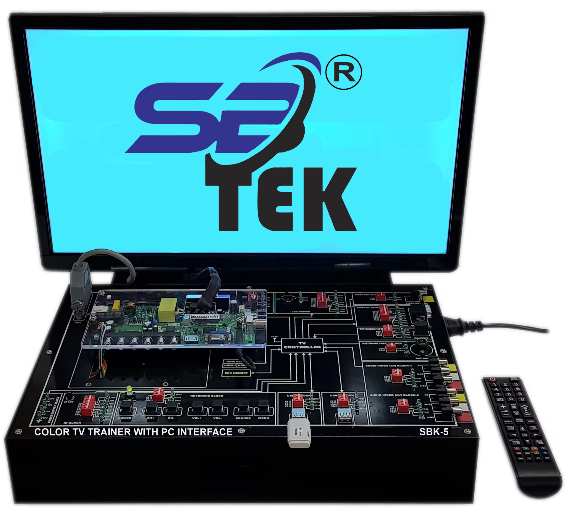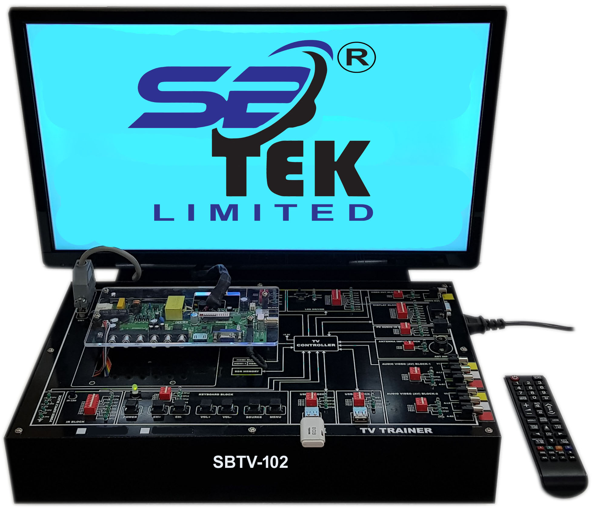
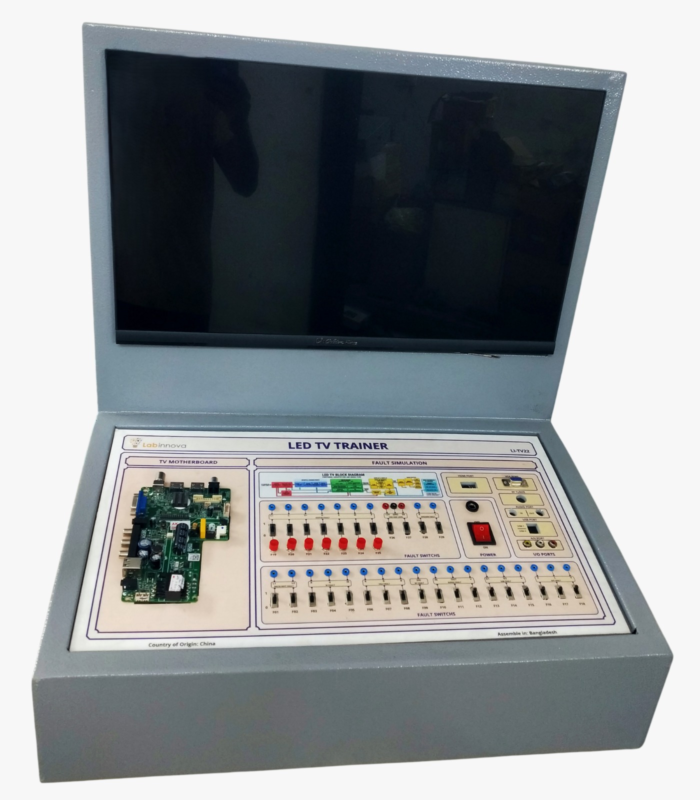
01. SYSTEM OVERVIEW: The SB-TV-21 is an LED TV trainer built around a superior-quality 24-inch full-HD LED color television / PC monitor, with solder-free fault simulation built directly onto the unit. Rather than a scaled-down mock-up, students work on the real receiver, IC, and display circuitry of a production-style LED TV, supporting both manual and remote-control operation, so every measurement and every fault reflects genuine field-service conditions rather than a simplified teaching model. A complete block diagram of the LED TV system is printed directly on the trainer board, allowing students to identify every part and section of the circuit at a glance — from the AC input and power-supply stage, through the backlight driver and T-CON board, to the video-processing, audio, and RF-tuner sections. This on-board mapping removes the need to constantly cross-reference a separate schematic sheet, so learners can trace signal flow and locate a given component in seconds, even early i
02. CORE HARDWARE SPECIFICATIONS
Parameter Specification
Display 24-inch, full-HD LED colour television / PC monitor
Operation Modes Manual and remote-control operation
Video Standards PAL / NTSC
Video Inputs Composite video input, VGA input
Circuit Reference Complete block diagram of the LED TV system printed on the trainer board
Fault Simulation Solder-free fault creation via on-board switches across 6 circuit blocks
Test Points Dedicated points for voltage measurement and waveform observation at each stage
03. KEY FEATURES
• Real 24? full-HD LED TV/monitor as the trainer platform, not a simplified mock-up
• On-board block diagram for quick visual identification of every circuit section
• Dedicated test points for voltage measurement and waveform observation at each stage
• Solder-free fault switches for safe, repeatable fault insertion during troubleshooting practice
• Supports both composite video and VGA input for flexible signal sourcing
• Dual PAL/NTSC video-format compatibility
• Manual and remote-control operation for realistic service-technician training
04. FAULT SIMULATION TABLE (11 FAULTS)
Instructors can insert any of the following solder-free faults to give students realistic, guided troubleshooting practice across six circuit blocks:
ID Circuit Block Fault Action / Switch Observed Symptom Diagnostic & Measurement Step
F01 Power Supply Open Fuse F101 Completely dead TV; no standby LED. Measure AC voltage at input; check for 0V at the main filter capacitor.
F02 Power Supply Open 5V Standby Rail Standby LED is off; TV will not turn on. Measure voltage at the 5V_STBY test point.
F03 Backlight Disconnect BL_ON Signal Sound is present; screen stays completely black. Check for 3.3V/5V at BL_ON pin when turning power on.
F04 Backlight Open LED+ Supply Line Flashlight test shows faint image; no screen light. Measure high DC voltage output at the LED backlight connector.
F05 System Control Open IR Data Line Remote control does not work; keypad works fine. Use an oscilloscope to check for data pulses at the IR receiver pin.
F06 System Control Short Keypad ADC Line Front buttons do not respond or perform wrong actions. Measure the voltage divider resistors on the keypad PCB.
F07 T-CON Board Open VGH Voltage Rail Screen goes white, fades out, or shows heavy ghosting. Locate VGH test point on T-CON; check for 20V to 30V DC.
F08 T-CON Board Open VGL Voltage Rail Screen shows slow refresh rate, glowing lines, or negative image. Locate VGL test point on T-CON; check for -5V to -15V DC.
F09 Video Processing Disconnect LVDS Blue Pair Screen output has a heavy yellow tint (missing blue). Check differential waveform signals across LVDS pairs using a scope.
F10 Audio Block Open VCC to Audio Amp Video is perfect; absolutely no sound from speakers. Verify 12V/24V DC supply at the VCC pin of the audio amplifier IC.
F11 RF Tuner Open AGC Line Input channels cannot be found; static or "No Signal" banner. Measure the Automatic Gain Control (AGC) voltage at the tuner pin.
05. ACCESSORIES & PACKAGE CONTENTS
• Remote control unit
• Power supply cord (mains)
• Composite video cable and VGA cable
• User manual + fault-finding/troubleshooting guide
• Probe leads for test-point measurement.