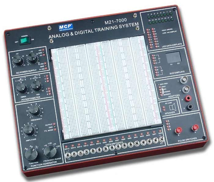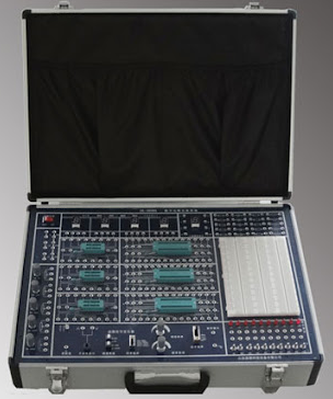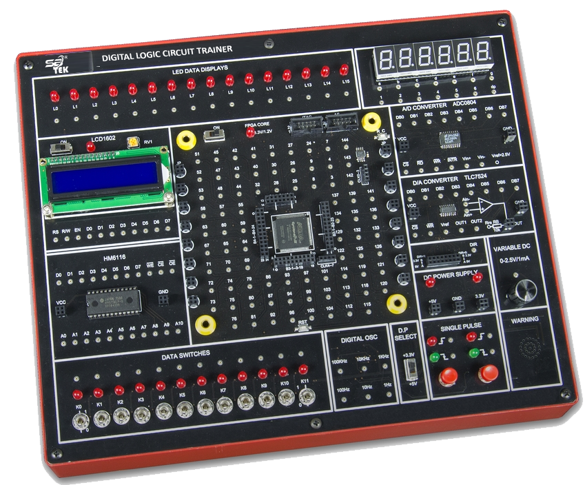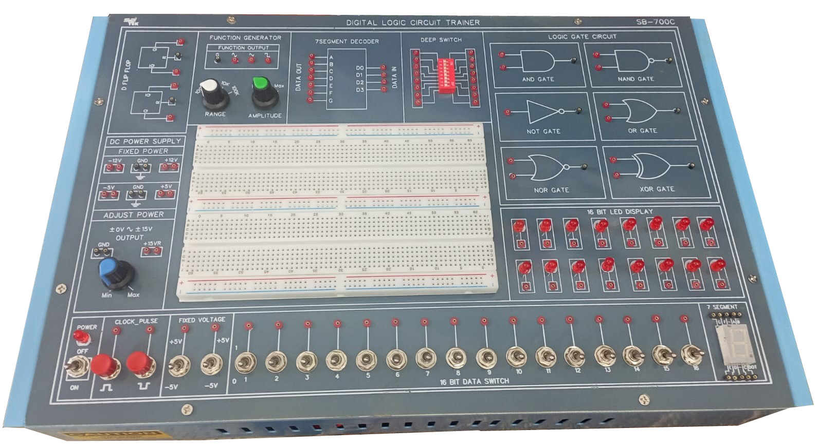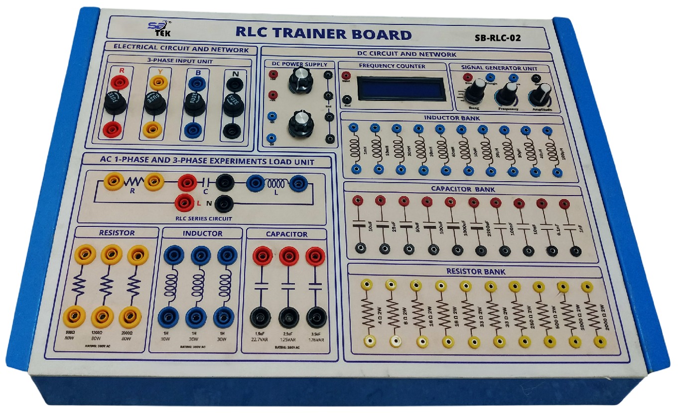
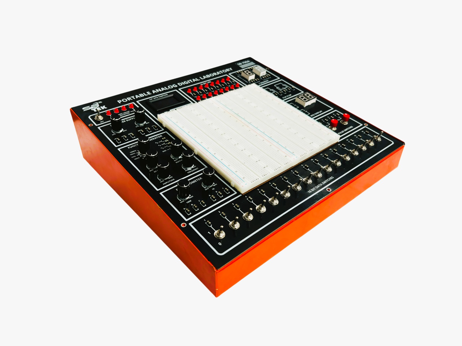
01. SYSTEM OVERVIEW: The SB-700A Portable Analog & Digital Laboratory Trainer is a compact, self-contained trainer kit designed for hands-on instruction in analog and digital electronics. Housed in a rugged, orange-trimmed portable enclosure, the unit consolidates a regulated DC power supply, function generator, digital voltmeter, and a comprehensive set of digital logic building blocks onto a single control panel, allowing students to design, wire, and test circuits without external lab equipment. The trainer is suitable for polytechnic, undergraduate engineering, and vocational-training laboratories covering courses in Digital Electronics, Analog Electronics, Logic Design, and Microelectronics fundamentals. Its all-in-one layout lets instructors move directly from concept to construction, giving learners repeated, guided practice with the same building blocks used across combinational logic, sequential logic, waveform generation, and applied analog circuit design.
02. CORE HARDWARE SPECIFICATIONS
Parameter Specification
Manufacturer SB TEK
Enclosure ABS/metal portable case with orange protective edge trim, carry-style housing
Power Input Mains-operated, internal regulated DC power supply
DC Power Supply Outputs Two independent variable supplies: +5V, +VR, GND, GND, -5V, -VR (MIN-MAX adjustable)
Short-Circuit Indication 4 LED indicators with ON/OFF mains switch
DC Voltmeter 5½-digit digital display with IN / GND probe terminals, 0-30V (approx.) range
16-Bit LED Display 16 individually wired red LEDs (numbered 0-15) for output-state monitoring
7-Segment Display Module One common-cathode and one common-anode display with individual segment (a-g, dp) input terminals
Flip-Flop Module Two hard-wired SR flip-flop blocks (Q, R?, S?, Q? terminals) for sequential-logic study
BCD Display Module Two 4-bit BCD-to-7-segment decoder/display channels (D1, D2) with A-B-C-D inputs
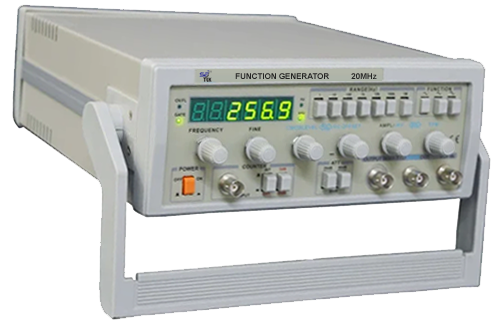
Function Generator Sine / Square / Triangle waveform selection; Range switch: 100 Hz / 1 kHz / 1 MHz; adjustable DC Bias, Duty Cycle, Amplitude and Frequency (MIN-MAX potentiometers); GND reference
Audio Output Built-in speaker with dedicated output terminals (A, B)
Potentiometer Bank Two panel-mounted pots — 100 k? and 1 k? — each with A/B/C wiper terminals
Pulse Switches Two momentary push-button switches providing debounced complementary outputs (A/?, B/B?)
16-Bit Data Switches 16 independent toggle switches (numbered 1-16) providing logic 0/1 inputs
Typical Applications Digital logic design, combinational & sequential circuits, waveform generation and analysis, analog biasing, mixed-signal experimentation
03. KEY FEATURES
• Fully portable, mains-powered unit with built-in short-circuit protection and visual indication
• Dual regulated DC power supply outputs (+5V/-5V and variable VR) for powering external circuits
• Digital DC voltmeter with dedicated probe terminals for direct in-circuit measurement
• 16-bit LED display bank for real-time visualization of logic states
• Common-cathode and common-anode 7-segment display modules with individually accessible segment pins
• Dual BCD-to-7-segment decoder/display channels for BCD interfacing experiments
• Built-in SR flip-flop blocks for sequential logic design
• Function generator with selectable sine/square/triangle waveforms, adjustable range, amplitude, frequency, duty cycle and DC bias
• Integrated speaker for audio/tone output experiments
• 100 k? and 1 k? potentiometers for analog biasing and potential-divider experiments
• Two debounced pulse push-buttons with complementary outputs for manual clocking
• 16-channel toggle-switch bank for static logic-level input
04. CONTROL PANEL LAYOUT
The front panel is organized into clearly labeled functional zones, each dedicated to a specific class of electronics experiment:
Panel Section Description
Power & Safety Mains ON/OFF switch, 4-LED short-circuit indication, regulated DC power supply section
Measurement Digital DC Voltmeter with IN/GND probe terminals
Display - Logic 16-Bit LED indicator bank (channels 0-15)
Display - 7-Segment Common-cathode and common-anode 7-segment display blocks with individual segment terminals
Display - BCD Two BCD-to-7-segment decoder/display channels (D1, D2)
Sequential Logic Dual SR flip-flop training block
Signal Source Function generator: sine/square/triangle, 100 Hz-10 kHz range, adjustable amplitude, duty cycle, DC bias and frequency
Audio Integrated speaker with output terminals
Analog Components 100 k? and 1 k? variable potentiometers
Input - Manual Pulse Two debounced pulse push-buttons (complementary outputs)
Input - Static Logic 16-channel toggle-type data switch bank
05. EXPERIMENT LIST & SUGGESTED EXERCISES
The SB-700A supports a broad range of laboratory exercises spanning combinational logic, sequential logic, waveform generation, and applied analog circuits. A representative course of experiments is listed below; instructors may extend or adapt this list to suit specific curricula.
Category Suggested Experiments / Exercises
Digital Logic Fundamentals • Study and verification of basic logic gates — AND, OR, NOT, NAND, NOR, XOR, XNOR
• Verification of Boolean algebra laws and De Morgan's theorems
• Realization of one logic gate using universal gates (NAND / NOR)
Combinational Circuits • Design and verification of Half Adder and Full Adder
• Design and verification of Half Subtractor and Full Subtractor
• Study of Multiplexer and Demultiplexer operation
• Study of Encoder and Decoder circuits
• BCD to 7-segment decoding and display using the BCD Display module
• Interfacing and testing common-cathode / common-anode 7-segment displays
Sequential Circuits • Study of SR flip-flop truth table and race-condition behavior
• Construction of JK, D and T flip-flops from the SR flip-flop block
• Design of a simple shift register using flip-flop stages
• Design of asynchronous (ripple) and synchronous binary counters
• Design of Ring counter and Johnson (twisted-ring) counter
Input / Output & Switching • Using the 16-bit data switch bank to generate arbitrary input logic states
• Observing circuit outputs on the 16-bit LED display bank
• Studying switch bounce and debouncing using the Pulse Switches
• Generating manual clock pulses for sequential-circuit experiments
Analog & Waveform Experiments • Study of sine, square and triangular waveform generation using the Function Generator
• Effect of Range, Amplitude, Frequency, Duty Cycle and DC Bias controls on generated waveforms
• Measurement of DC voltages using the built-in Digital DC Voltmeter
• Study of potential-divider action using the 100 k? and 1 k? potentiometers
• Loading a waveform / tone onto the built-in speaker
Power Supply & Applied Circuits • Study of a regulated dual DC power supply (+5V/-5V, variable VR outputs)
• Powering external breadboard circuits (e.g., op-amp, timer, transistor circuits) from the on-board supply
• Building an astable/monostable multivibrator (e.g., 555 timer) using the on-board supply and voltmeter
• Verifying short-circuit protection and indication
06. ORDERING INFORMATION & NOTES
• Model No.: SB-700A — Portable Analog & Digital Electronics Laboratory Trainer
• Recommended accessories (sold separately): breadboard, jumper wires, digital IC set (74xx series), and resistor kit
• Unit operates on standard mains supply; internal regulation provides safe experimental voltages
• Recommended for classroom sets in Digital Electronics, Analog Electronics, and Basic Electrical Engineering laboratories